Geomatics Specialist
Aerial photography camera
Aerial photography camera, Antarctica
Aerial photography at the British Antarctic Survey
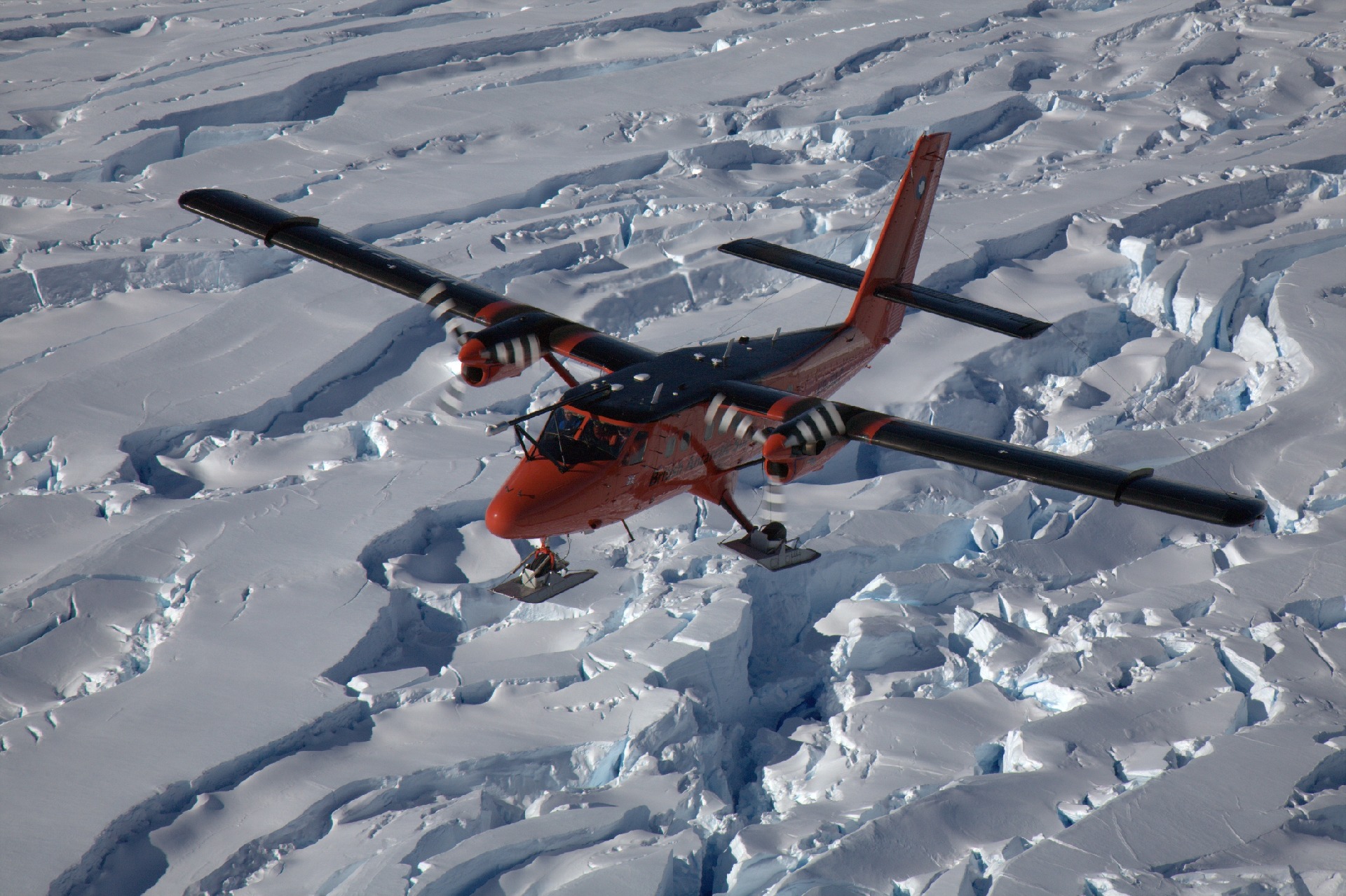
The British Antarctic Survey owns and operates a Zeiss RMK large format aerial photography camera. The camera can be fitted to two of the four BAS Twin Otter aircraft. It was originally designed by Zeiss for topographic mapping. As well as for topographic mapping, BAS uses aerial photography taken with this camera for geological and vegetation mapping, interpreting satellite imagery and counting populations of penguins and seals. BAS collaborates with the UK Hydrographic Office to fly aerial photography for hydrographic charting.
The Zeiss camera system
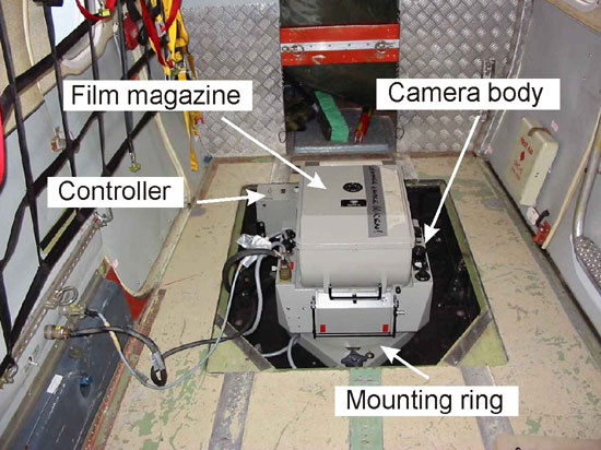
The camera system is made up five parts. In all the system weighs well over 100 kg.
Mounting ring
The camera sits on a motorised mounting ring in a pit in the aircraft floor. The camera looks vertically downwards through a port in the aircraft belly. The mounting ring is self-levelling to keep the camera level during flight and can be rotated to compensate for crabbing in the aircraft flight. (Crab occurs when cross-winds make the aircraft fly slightly rotated to the direction of flight). Tilt and crab of the camera affect the area coverage of the photographs and must be compensated for by the camera system.
Camera body and lens
The camera body contains the shutter system and the lens cone. The lens is 153 mm (6 inches) focal length, which gives a photograph scale of 1:10,000 at 5,000 feet (1524 m) flying height, 1:20,000 at 10,000 feet (3048 m). The lens is complex and made up of several elements which together give very high image resolution with minimal distortion.
The camera has a special shutter which opens and closes radially, this minimises time-lag in opening the shutter and reduces blurring of the image due to travel of the aircraft during the time that the shutter is open.
The camera has a maximum shutter speed of 1/1000 second and an aperture range of f? to f? The shutter speed and aperture can be set manually or calculated automatically by the camera using a light sensor in the lens housing.
The lens has various filters for hazy conditions and to equalise the amount of light captured across the large lens (anti-vignetting filter), but a clear anti-vignetting filter is normally used for operations on the Antarctic Peninsula where the air is very clear and the light good.
Film magazine
The camera uses roll film that is 24 cm (9.5 inches) wide, BAS usually uses 75 m or 80 m rolls, giving about 300 photographs per roll. The magazine contains a complex series of rollers to move the film quickly and smoothly across the camera back between exposures and a vacuum system to ensure each negative is completely flat at the moment of exposure.
-
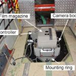
- Zeiss RMK camera in a BAS Twin Otter aircraft. Looking towards the aircraft tail.
Controller
The controller uses information received from the navigation sight and the camera settings to calculate the time interval needed between successive photographs to keep full overlapping coverage.
Navigation sight
The navigation sight is used by the camera operator to navigate along the planned survey flight-lines. It is fitted at the front of the aircraft and has a periscope head, which looks downwards and forwards. It can be retracted during take-off and landing and lowered during flight so that the Twin Otter landing ski does not block the view. The camera operator can see the terrain ahead, match it to the planning map and tell the pilot of any adjustments needed to the aircraft track. The camera operator and pilot talk to each other through headsets.
The navigation sight is also used to compensate for crab of the aircraft. The operator rotates the navigation sight to point in the direction of travel and the camera mount follows with the same rotation.
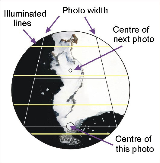
Lastly, the navigation sight allows the time interval between photographs to be varied to keep coverage without gaps or a specific overlap between photographs. As the aircraft flies over a mountain the ground clearance is less and the photographs have to be taken closer together to avoid gaps, as it goes over a valley or low area, the time interval can be increased again. The navigation sight has an ingenious method for doing this. Illuminated lines move through field-of-view. The operator adjusts the speed of travel of the lines to match the speed of travel through the field-of-view of objects on the ground such as rock outcrops or crevasses. The controller unit described above uses this information to trigger the camera at the correct time intervals to keep the desired coverage.
-
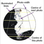
- View through the navigation sight. Note the illuminated lines, used to set the time interval between photographs.
Flying aerial photography
Sometimes the features to be photographed, such as a rock outcrop or a penguin colony, can be covered by a single strip of photographs. More often, for example for topographic mapping, the area to be covered is wider than the ground footprint of a single strip of photographs. Here, area coverage has to be built up by flying several strips of aerial photographs with an overlap between each to avoid gaps.
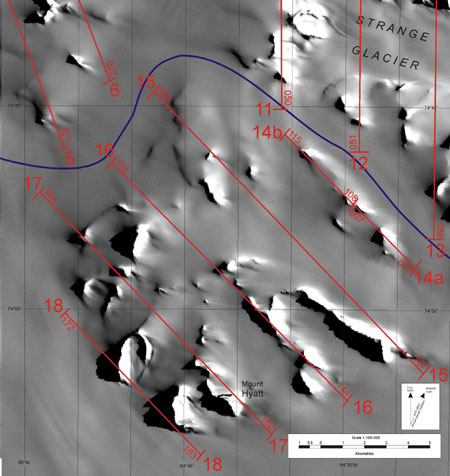
Before flying the aerial photography a detailed flight plan is prepared at 1:100,000 scale showing the survey lines needed for the area and a calculation of the number of photographs. We usually use Landsat satellite imagery as the backdrop for these maps. During flight the pilot follows the flight plan, linking the lines in the most efficient way. The camera operator uses the navigation sight to check progress and tells the pilot of any adjustments needed to the aircraft track.
-
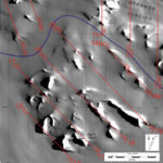
- Part of a BAS aerial photography flight plan, showing parallel flight lines to build up area coverage.
During the flight, the position of the aircraft is tracked by a GPS receiver that is linked to the camera. The GPS detects and records the instant of exposure of each photograph. A GPS ground station records data from the same satellites during the flight. After the sortie, the GPS readings are processed with reference to the base-station and the position of the camera for each photograph can be calculated to a few centimetres accuracy. As well as giving a useful record of the location of each photograph, this has important benefits for topographic mapping by reducing the number of ground-surveyed reference points needed to make an accurate map.
-
-
Head of MAGIC
-
Building data resources for managing the South Georgia & South Sandwich Islands Marine Protected Area
Read more of: Building data resources for managing the South Georgia & South Sandwich Islands Marine Protected AreaThis project ensures the protection and conservation of the region’s rich and diverse marine life, whilst allowing sustainable fisheries.